 |
Building an MJ Model |
Hints & Tips
Errata |
These pages have been put together from information gathered from people who have built or are building an MJ model. They contain useful building instructions, drawing error corrections and other information.
It is by no means a complete list of modifications but should be of use to an MJ builder. I will update this section when I get more mods.
As far as possible the information is checked before adding to this section but no responsibilty can be accepted for any consequenses arising from use of this information.
click on a section
2" Burrell Gold Medal Tractor
2" Fowler A7 Agricultural Engine
Notes from Clive Manser - 10th March 2010
1. Smokebox Door Hinge.
The pitch of the rivets, as shown on the drawing, for the smoke box door ring is incompatible with the positioning of the smoke box door hinge. The drawing shows the hinges to be fastened to the side of the smoke box at one-inch centres, whereas, in practice I found 0.875" centres allowed the hinges to just clear the door ring rivets.
2. Valve Rods
The drawing for the valve rods will drive you crazy. The centre lines are confusing but after much thought I came to the conclusion that the 7/32" dimension for the number 2 Forward Rod should in fact be 15/64". In any event you may have to bend the rods very slightly to obtain a perfect fit to the expansion link.
2" Fowler A7 Road Loco
3" Fowler A7 Agricultural Engine
Drawing 0905 - Gearing
2nd Shaft
The dimension for the keyway on the right hand end should read 1 13/32".
Drawing 0907 - Cylinder
Cylinder Liner
A major change is that we have decided that the flanged head on the liner is not really necessary and the cast iron bar that we supply for the liner has been reduced in size accordingly. This means that you do not have to machine the counterbore in the front end of the cylinder bore to accommodate this flange. All other details of the liner remain unchanged.
Rear Cylinder Cover
The dimension for the slidebars to fit in was 11/16" should be 5/8" the size of the slidebars.
Drawing 0909 - Motion
Weighshaft Bracket
The measurement for the slide bars to fit into was 2 13/16" it should be 2 3/4". If you add up the two slide bars, the crosshead and the crosshead slippers, i.e. 5/8" + 5/8" + 1 3/8" + 1/16" + 1/16" = 2 3/4".
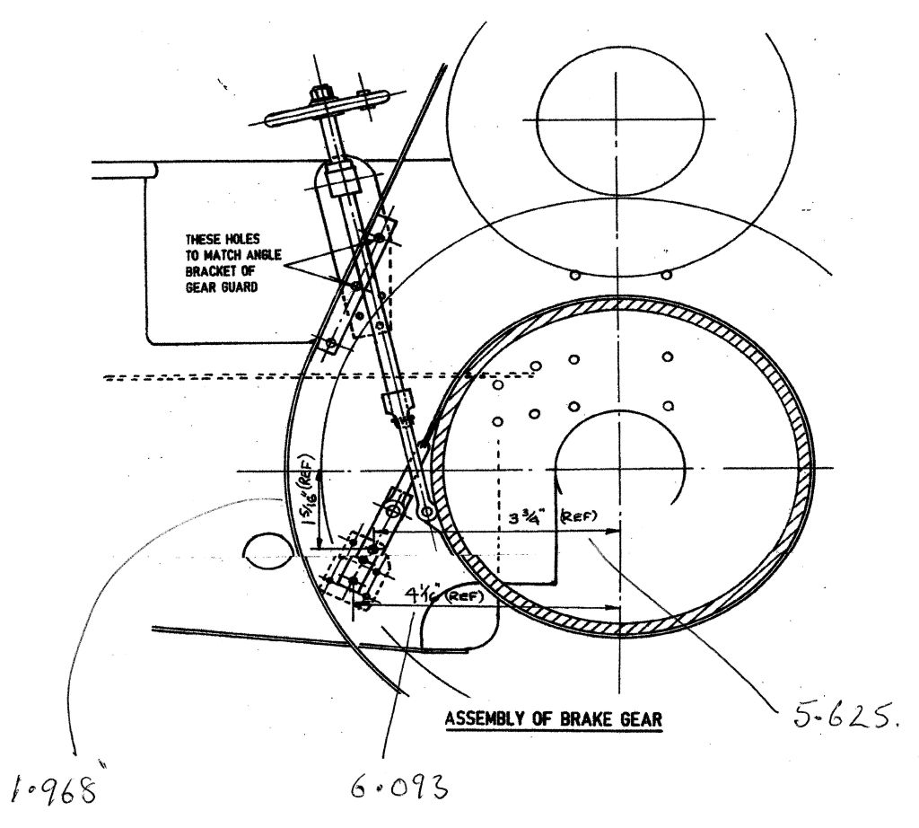
Drawing 0910 - Brake Gear etc
Bottom Brake Band Fixing Position
Fred Nightingale has pointed out that there are three dimensions missing that are on the 2" drawing which help to position the bottom brake band fixing. The 2" values are shown with Fred's 3" dimensions hand drawn.
3" Wallis & Steevens
Ariel - 5" Gauge Rebuilt Merchantd Navy Loco
General Drawing Errors
There are quite a few errors in the drawings by Keith Wilson. I was given a list of some when I took over MJ.
Download Error ListRob Speare, one of my customers, has put together a very comprehensive web site about Bulleid Locos and there derivatives. Also some notes on building the models from a number of other builders. Well worth a look if you are building the Ariel or are thinking about a new project.
The website is here
Bulleid Locos
7 1/4" Gauge Bagnall Loco
Banall Price Valve Gear
One of my customers has identified an error in the dimensions of the Bagnall Price Valve Gear.
Using an on-line Valve Gear analysis program by Charlie Dockstaders, he has drawn up a list of the relevant dimensions.
If the program dimensions (highlighed in green) are used then it works better.
| Program Description | Drawing Description | Drawing Dimension | Program Dimension |
| Driver | Wheel Dia | 6.325 | 6.325 |
| Stroke | Crankpin Rotation Radias | 3.25 | 3.25 |
| Main Rod | Connecting Rod | 14.75 | 14.75 |
| Motion Connect Rod length | Pendulum Lever connecting link | 6.875 | 6.875 |
| Vertical | | 0 | 0 |
| From Crosshead | | 1.375 | 1.375 |
| Fulcrum lever upper | | 0.34 | 0.38 |
| Fulcrum lever backset | | 0 | 0 |
| Fulcrum lever lower | | 2.563 | 2.546 |
| Fulcrum diameter | | 1.125 | 1.125 |
| Radias Rod length | Radial Rod | 9.813 | 9.813 |
| Radias Rod extension | | 0 | 0 |
| Link Radias | | 9.813 | 9.813 |
| Link Rocking Lever length | Rocking Shaft Lever | 1.25 | 1.25 |
| Link Rocking Lever angle | | 75 deg | 75 deg |
| Eccentric Rod length | | 7.118 | 7.286 |
| Eccentric circle dia | | 1.000 | 1.000 |
| Eccentric diameter | | 2.5 | 2.5 |
| Eccentric angle | | 129.10 | 129.10 |
| Reversing Arm vertical | Weighshaft Lever height | 1.313 | 1.313 |
| Reversing Arm backset | | 0 | 0 |
| Lifting Arm length | Weighshaft Lever length | 2 | 2 |
| Lifting Link | Suspension Link | 2.875 | 2.875 |
| Reverse Arm pivot vertical | Axle to weighshaft centre vertical | 6.063 | 5.269 |
| Reverse Arm pivot horizontal | Axle to weighshaft centre horizontal | 8.25 | 8.821 |
| Fulcrum centre pivot vertical | Axle to Rocking Shaft centre vertical | 3.0 | 2.335 |
| Fulcrum centre pivot horizontal | Axle to Rocking Shaft centre horizontal | 6.5 | 6.768 |
| Reverse Arm to centre normal | | 0.8 | 0.8 |